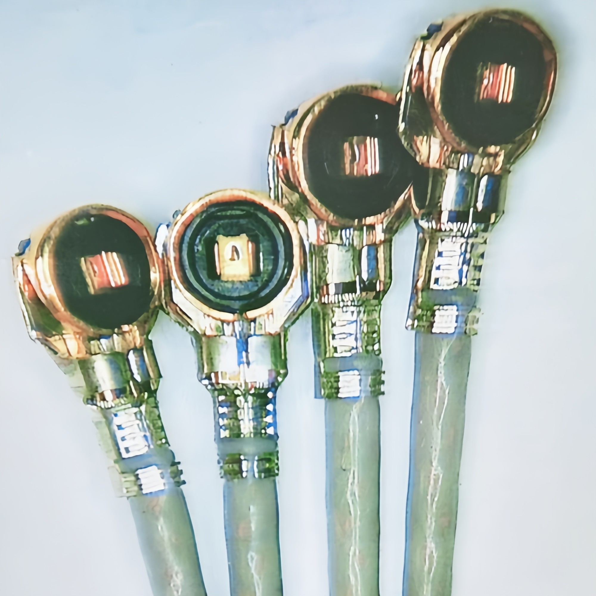
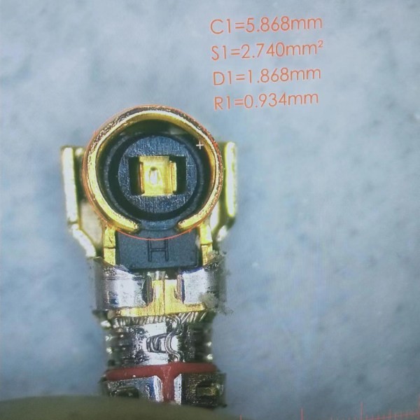
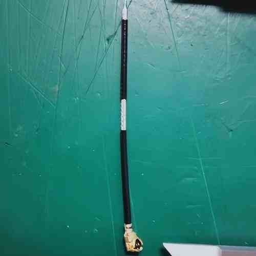
IPX Cable Assembly
IPEX Cable Assembly
MHF 1-5 Generations
Cable O.D 1.13/1.37/1.78/0.81/0.64
IPEX Cable Assembly
MHF 1-5 Generations
.
Electrical Performance EIA364
Contact
Resistance Solder the receptacle connector to the test board and mate
the plug connector together,then measure the contact
resistance as shown in this by the four terminal method。
Open circuit voltage: 20mV MAX
Circuit current: 10mA MAX
Inner contact:Initial:20mΩ MAX After:25mΩ MAX
Ground contact:
Initial:20mΩ MAX After:25mΩ MAX
5.2 Insulation Resistance
Mate the plug and receptacle connector together,and then,
apply DC 200 V Voltage between the inner contact and the
ground contact in accordance with EIA 364-21
EIA364-21, 200V DC Initial:500 MΩ MIN After:100 MΩ MIN
5.3 Dielectric
withstanding voltage Mate the plug and receptacle connector
together,and then apply AC 200 V between the inner contact
and the ground contact in accordance with EIA 364-20
EIA364-20 200V AC No flashover, No sparkover, No excess leakage, No breakdown
5.4 V.S.W.R
Measure the V.S.W.R by the network analyzer Frequency:0~9GHz
V.S.W.R,DC~9GHz.
Note: 1. Cable type Connectors were measured with SMA
conversion adapters attached to both ends of the harness
product of a suitable 100mm cable.
DC~3GHz:1.3MAX
3~6GHz:1.4MAX
6. Mechanical Performance
6.1 Un-mating Force
Solder the receptacle connector to the test board and mate
the plug connector, then measure the un-mating force at
speed 25±3mm/minutes along by the push-push machine
1.Initial:4N MIN 2.After 30 Cycle:2N MIN
6.2 Crimp strength
Pull the cable as shown in this at speed of 25±3mm/minute
through tensile strength machine. 7N MIN
6.3 Durability
Mate and un-mate the receptacle connector(soldered to the
test board) and plug connector 30 cycles at the speed of
25± 3mm/minutes along the mating direction by the
push-push machine Appearance:No abnormality
Contact Resistance:Shall meet 5.1
6.4 Cable retention force
After the Connectors are mating, do not apply a load to
the cable in excess of the values indicated in the diagram
below. No electrical
discontinuity grater than 1μs shall occur
Inquiry
Products
CATALOGUE
- Antenna
- WIFI antenna
- Box antenna series
- SMA-J antenna series
- Rubber rod antenna series
- FPC antenna series
- Steel plate antenna series
- spring antenna series
- PCB antenna series
- LDS antenna series
- Connectors
- 2.92 Connector
- TNC series RF coaxial connector
- 2.4mm connector
- SMA CONN
- BNC
- MCX
- MMCX
- CONNECTOR
- RF CONNECTORS
- Coaxial Cable Assembly


